
MenuProduct Center
- Monitoring signal lightning protection device
- Power surge protector
- Rail signal lightning protection device
- Equipotential connector
- Antenna-fed lightning protection device
- New energy lightning protection device
- Lightning rod and grounding material
- PDU lightning protection strip
- Backup protector
- Intelligent lightning protection box
- LED street light lightning protection device
Your location:Home → Products → Monitoring signal lightning protection device
Description
Product description
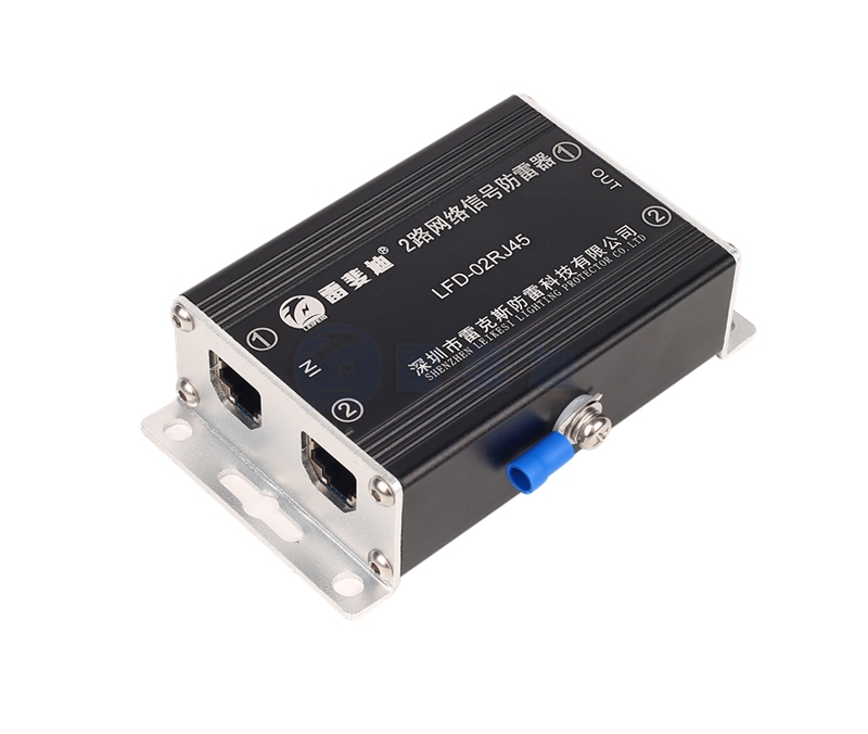
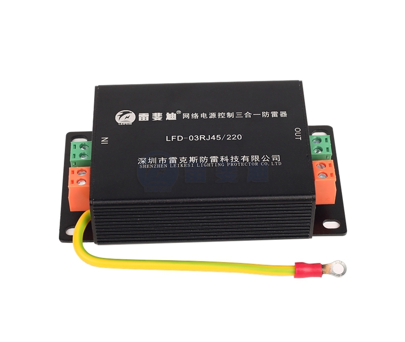
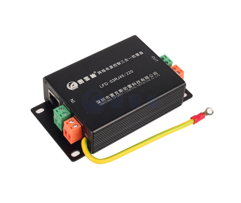
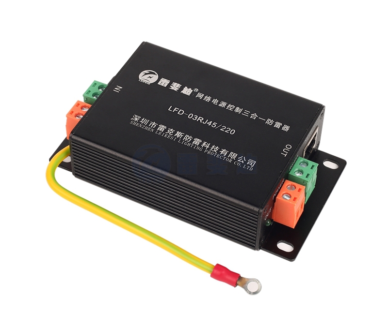
Lefedi’s three-in-one network lightning protection device is designed with reference to the national standard GB/T18802.21-2004/IEC61643-21:2000. It is suitable for the front-end network dome of the monitoring system, the power line of the wireless remote control camera, and the lightning surge of the network line. Protect it from damage caused by induced overvoltage, operating overvoltage and electrostatic discharge; at the same time, it has lightning protection for signal power supplies of different voltage levels.
Features
○ Easy flow, high-speed response, low loss;
○ Three-level surge protection, low residual voltage, fast response time and long service life;
○ Integration, small size, simple wiring, convenient installation, and reduced space occupation.
Technical Parameters
| model | LFD-03RJ45/220 | LFD-03RJ45/24 | LFD-03RJ45/12 | ||||
| Features | Power/Network | Power/Network | Power/Network | ||||
Nominal working voltage UN | 220V | 5V | 24V | 5V | 12V | 5V | |
Maximum continuous operating voltage Uc | 380V | 6V | 30V | 6V | 30V | 6V | |
Nominal load current IL | 2A | 2A | 2A | ||||
Nominal discharge current(8/20μS) In | 5KA | ||||||
| Maximum discharge current(8/20μS)Imax | 10KA | ||||||
| Voltage protection level(In)Up | ≤900V | ≤15V | ≤90V | ≤15V | ≤90V | ≤15V | |
| Response time Ta | ≤25ns | ≤10ns | ≤25ns | ≤10ns | ≤25ns | ≤10ns | |
| Transmission rate Vs | 100Mbps | 100Mbps | 100Mbps | ||||
| Insertion loss Ae | ≤0.3db | ≤0.3db | ≤0.3db | ||||
| Interface Type | Terminals | RJ45 | Terminals | RJ45 | Terminals | RJ45 | |
| Installation specifications | 1.5-4mm2 | 1.5-4mm2 | 1.5-4mm2 | ||||
| Transmission rate | 100Mbps | 100Mbps | 100Mbps | ||||
| Dimensions | 102*55*25mm | ||||||
| Shell material | Aluminum alloy | ||||||
| Temperature range | -40℃…+85℃ | ||||||
Wiring diagram

Installation, use and maintenance
1. Before connecting the protector to the system, check the grounding resistance of the ground grid, and it should meet the requirements of the specification.
2. Connect the grounding wire of the protector to the protective grounding bus of the machine room as short as possible.
3. There are input (IN) and output (OUT) signs on the protector, and the output terminal is connected to the protected equipment. Otherwise, the protector will be damaged and the equipment will not be protected.


 0755-21042597