
MenuProduct Center
- Monitoring signal lightning protection device
- Power surge protector
- Rail signal lightning protection device
- Equipotential connector
- Antenna-fed lightning protection device
- New energy lightning protection device
- Lightning rod and grounding material
- PDU lightning protection strip
- Backup protector
- Intelligent lightning protection box
- LED street light lightning protection device
Your location:Home → Products → Antenna-fed lightning protection device
Description
一、Product Usage
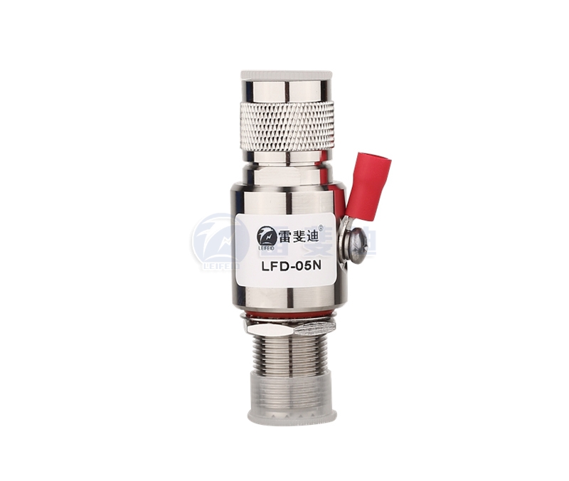
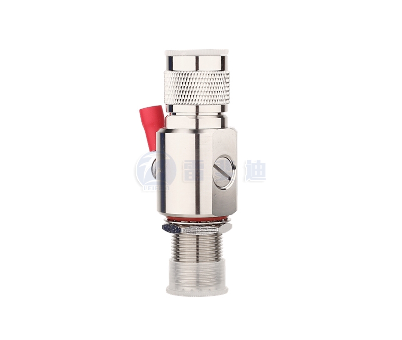
The lightning protection device for the antenna feeder is mainly used for the lightning protection of the feeder. It is suitable for wireless communication, mobile base station, microwave communication, radio and television and other coaxial antenna feed signal lightning and surge protection.
二、Features
1. Large flow capacity and multi-level protection;
2. The core components adopt international well-known brands with superior performance;
3. Low insertion loss to ensure smooth circuit;
4. Built-in fast semiconductor protection device, fast response speed and low residual voltage;
5. Energy saving, environmental protection, easy installation, suitable for various standard interface types;
6. The standing wave coefficient is small and the working frequency range is wide.
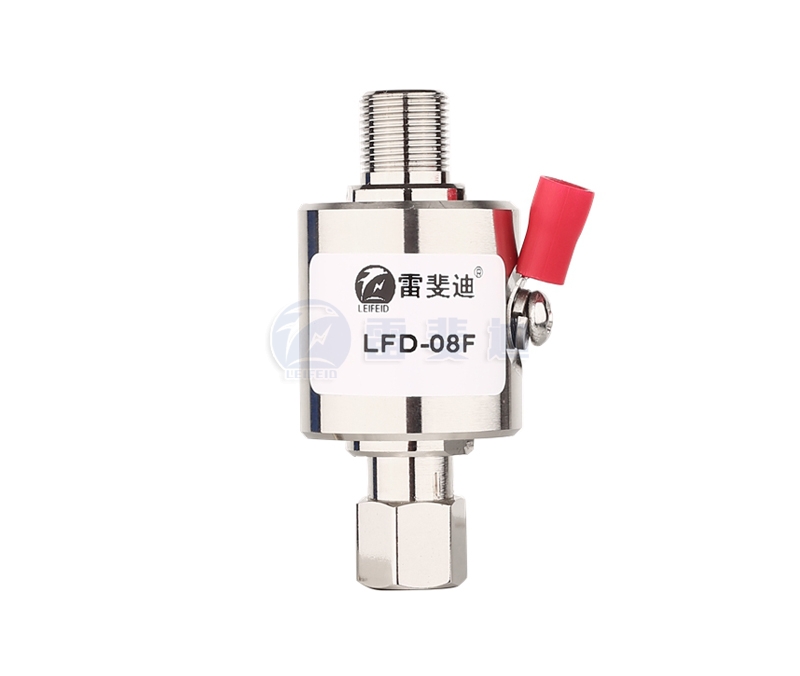
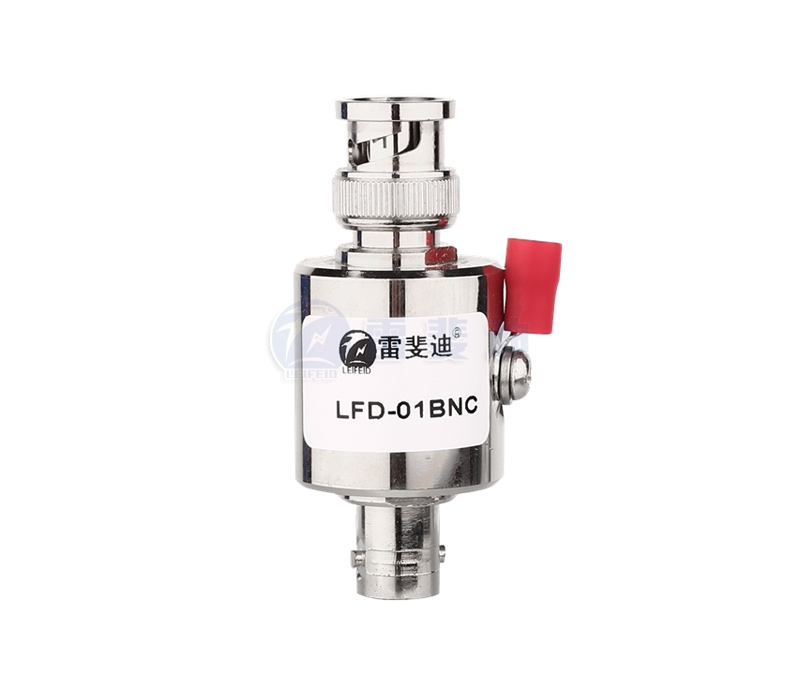
三、Technical parameters of antenna feed signal lightning protection device
| model | LFD-01BNC | LFD-02MSA | LFD-05N | LFD-08F | |||
| Maximum continuous working voltage Uc | 64V | ||||||
| Nominal flow capacity(8/20μs) In | 5KA | ||||||
| Maximum flow capacity(8/20μs)Imax | 10KA | ||||||
| Voltage protection level(1KV/Isn)Up | ≤600V | ||||||
| Response time Ta | ≤100ns | ||||||
| Insertion loss Ae | ≤ 0.3dB | ||||||
| Working temperature zone | -40℃…+80℃ | ||||||
| Characteristic impedance Z | 50Ω | ||||||
| Maximum transmission power P | 150W | 200W | 400W | 200W | |||
| Interface form | F | BNC | V | SMA | |||
| Installation method | Desktop installation, serial | ||||||
| Protection circuit | Single way | ||||||
| Shell material | Shield alloy | ||||||
1. Before connecting the lightning arrester to the system, check the grounding resistance of the grounding grid, which should meet the requirements of the specification.
2. Connect the lightning arrester to the front end of the protected equipment, and it must be connected reliably.
3. Connect the ground wire of the lightning arrester to the protective ground bus of the equipment room as short as possible. The grounding must be reliable. The grounding wire should be short, thick, and straight to reduce the influence of distributed inductance on lightning discharge; when installing the grounding wire, disconnect the equipment to avoid damage to the equipment due to the introduction of strong currents such as electric welding from the grounding wire.
4. Installation, use and maintenance
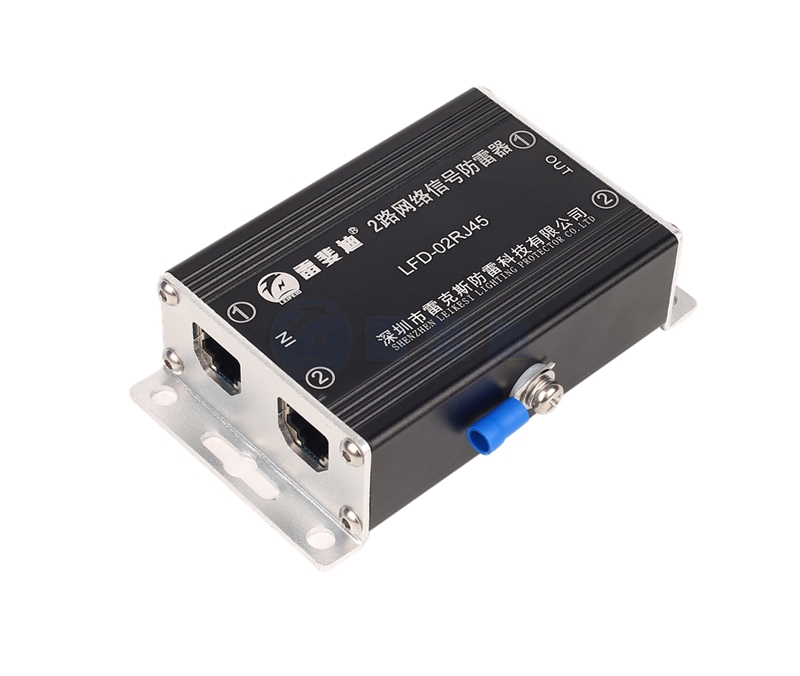
There are input (IN) and output (OUT) signs on the lightning arrester, and the output terminal is connected to the protected equipment, do not connect it reversely. Otherwise, the lightning arrester will be damaged and the equipment will not be protected. During installation, the lines at both ends must be laid separately and cannot be tied together to prevent secondary induction.
Wiring diagram


 0755-21042597