
MenuProduct Center
- Monitoring signal lightning protection device
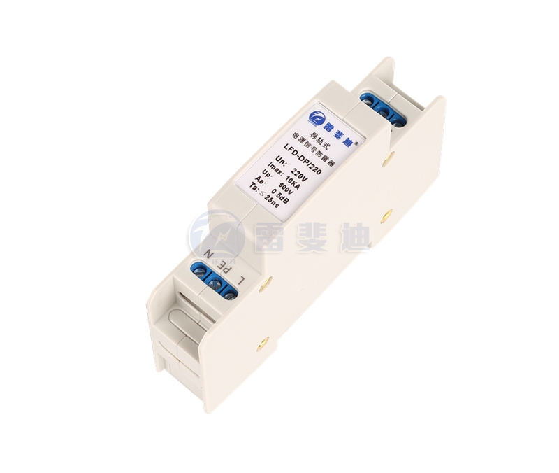
- Power surge protector
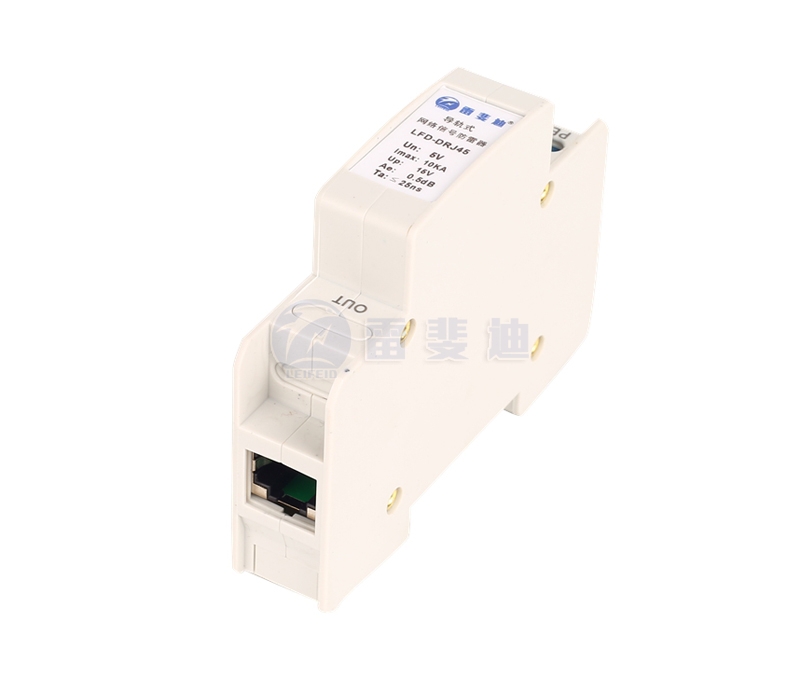
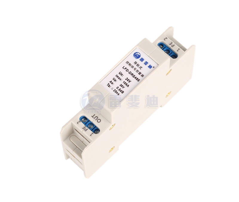
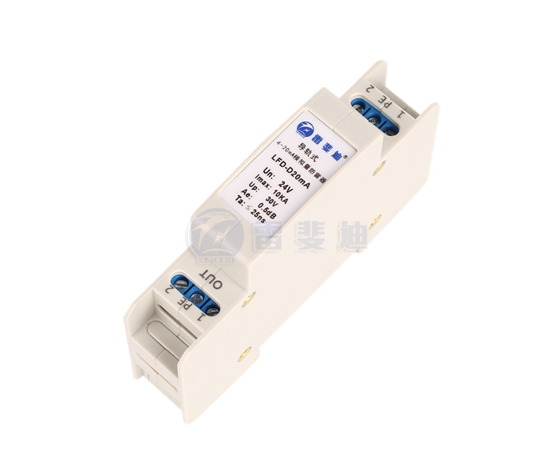
- Rail signal lightning protection device
- Equipotential connector
- Antenna-fed lightning protection device
- New energy lightning protection device
- Lightning rod and grounding material
- PDU lightning protection strip
- Backup protector
- Intelligent lightning protection box
- LED street light lightning protection device
Your location:Home → Products → Rail signal lightning protection device
Description
Product description
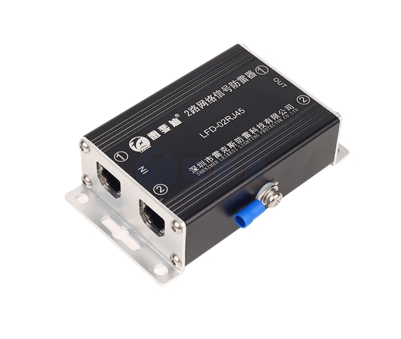
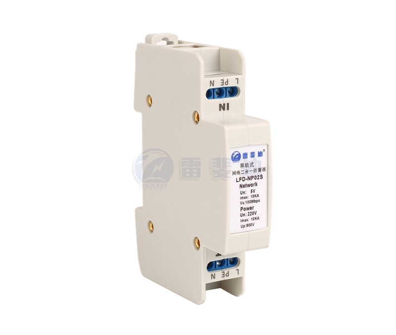
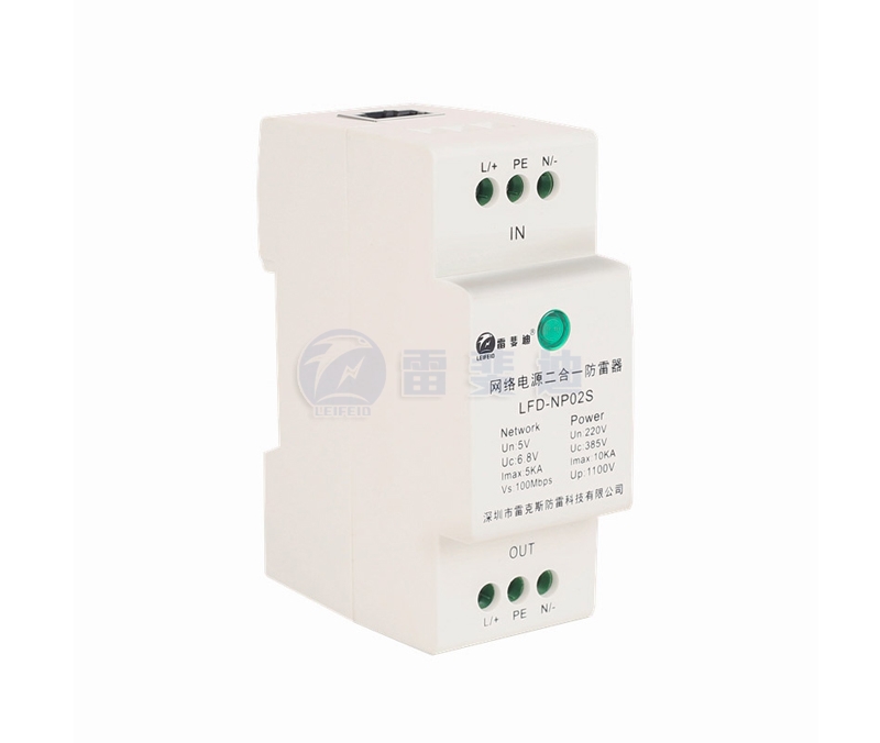
The two-in-one lightning protection device for Lefedi guide rail network is designed according to the national standard GB/T18802.21-2004/IEC61643-21:2000. A composite lightning arrester suitable for surge protection of the network signal line and power supply equipment of the Ethernet power supply line. The internal structure contains two protection schemes for the network line and the power line to ensure accurate protection of the system from overvoltage and avoid induction Damage caused by over-voltage, operating over-voltage, and electrostatic discharge; at the same time, it has lightning protection for signal power supplies of different voltage levels.
Application field
Power over Ethernet line, network data line, power supply line
Features
◎ Multi-level protection, large flow capacity
◎ Low limit voltage and fast response time
◎ Low insertion loss, superior signal transmission performance, stability, and long service life
◎ Beautiful structure, easy to install and maintain
Technical Parameters
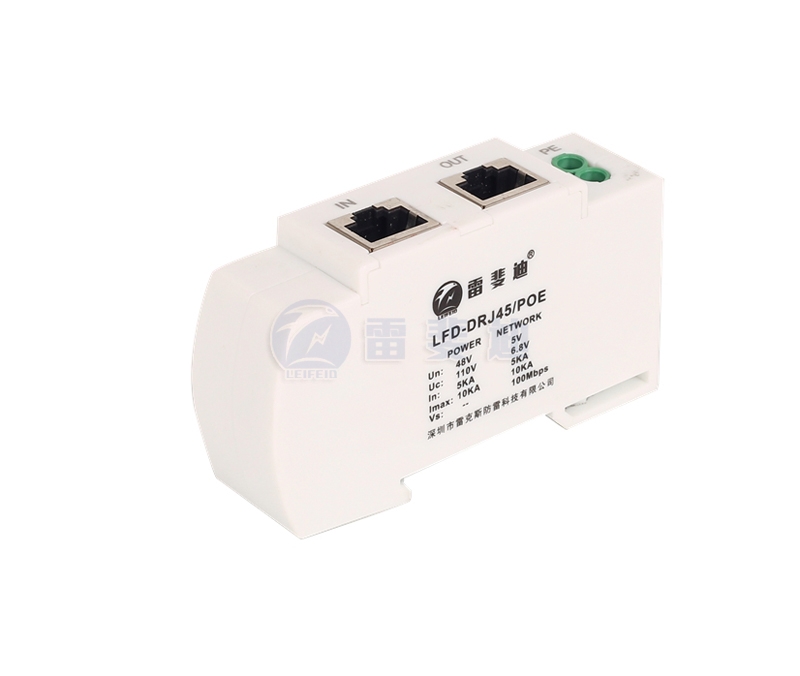
| Model number | LFD-DRJ45/POE | ||||
| The internet | power supply | ||||
| Rated working voltage Un | 5V | 48V | |||
| Maximum continuous operating voltage Uc | 6V | 60V | |||
| Maximum discharge current Imax | January 2 | 0.3KA | 4--5 | 0.3KA | |
| (8/20ms) | March 6 | 0.3KA | July 8 | 0.3KA | |
| 1、2、3、6、4、5、7、8-PE | 10KA | 1、2、3、6、4、5、7、8-PE | 10KA | ||
| SE-PE | 5KA | SE-PE | 5KA | ||
| Limit voltage Up10/700/ms | January 2 | <20V | 4--5 | <110V | |
| March 6 | <20V | July 8 | <110V | ||
| Insulation resistance MΩ | ≥0.4 | ||||
| Transmission rate Vs | 100M 1000M | ||||
| Insertion loss dB | ≤0.5 | ||||
| Near-end crosstalk dB | ≥60(PASS) | ||||
| bandwidth FG | (0.3~100)M | ||||
| Response time Ta | ≤1ns | ||||
| Enclosure rating | IP20 | ||||
| Dimensions | 90×51×24mm | ||||
| Shell material | Flame retardant PA66 | ||||
| Protection pair | 2对(1-2、3-6) | 2对(4-5、7-8) | |||
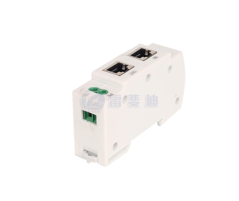
| Interface method | RJ45 | RJ45 | |||
Installation, use and maintenance
1. Installation instructions
Before connecting the protector to the system, check the grounding resistance of the ground grid, and it should meet the requirements of the specification. To connect the protector to the front end of the protected equipment, the connection must be reliable. Connect the ground wire of the protector to the protective ground bus as short as possible.
2. Matters needing attention
There are input (IN) and output (OUT) signs on the protector, and the output terminal is connected to the protected equipment. Otherwise, the protector will be damaged and the equipment will not be protected. If the loss increases due to poor connection of the plug socket and other factors, the protector should be reconnected or replaced. The user is not allowed to disassemble the fasteners of each part of the protector at will to avoid damage and affect normal work.
Wiring diagram


 0755-21042597